はじめに
今回は、LoRaWANゲートウェイに搭載のModbus通信のTCPモードで、LoRa Buttonからのデータを別端末のNodeREDに送信する方法をまとめています。
LoRaWANゲートウェイのModbus通信については以前の記事をご参照ください。
LoRaWANゲートウェイの設定
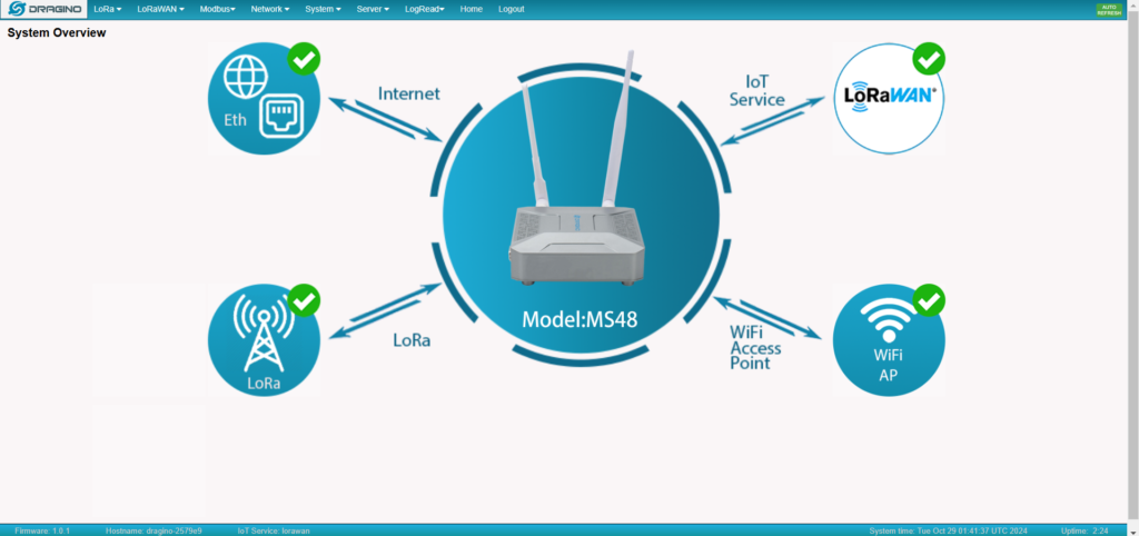
まず、LoRaWANゲートウェイのIPアドレス先に接続します。
カテゴリから、Modbus の設定を開きます。
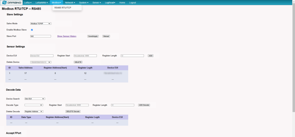
Slave Mode を TCP/IP に、Slave Port を 502 に設定し、Enanle Modbus Slaveにチェックを入れておきます。

Sensor Settings にて LoRa Button側面に記載された Device EUI と、
Register Start に 0000、Register Length に 12を入れて ADDします。

Accept FPort にて、Device EUIを選択した後、
確認した FPort を入力して ADD Accept Port します。
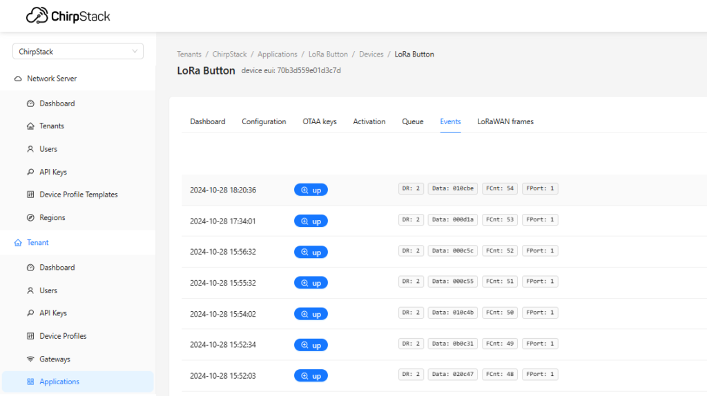
FPort については、LoRaWANサーバー (Chirp Stack) の受信データ欄横に記載されています。
ローカルのNodeREDでデータ受信を検証した際の受信データ内にも記載があります。

最後に、Save&Apply をクリックして設定を適用します。

NodeREDフローの設定
Node-REDを使ってModbusのMasterとSlaveの検証をしてみた
以前アップロードした記事を参照してフローを作成します。
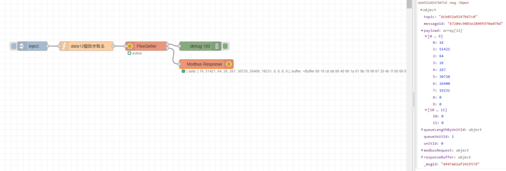
今回データを受信するにあたって、node-red-contrib-modbus の、受信用ノードのFlex Getter と、フロー上でJSON形式にデータを可視化する Modbus Response を使用しています。
Modbus Response ノードは動作には関係ありません。
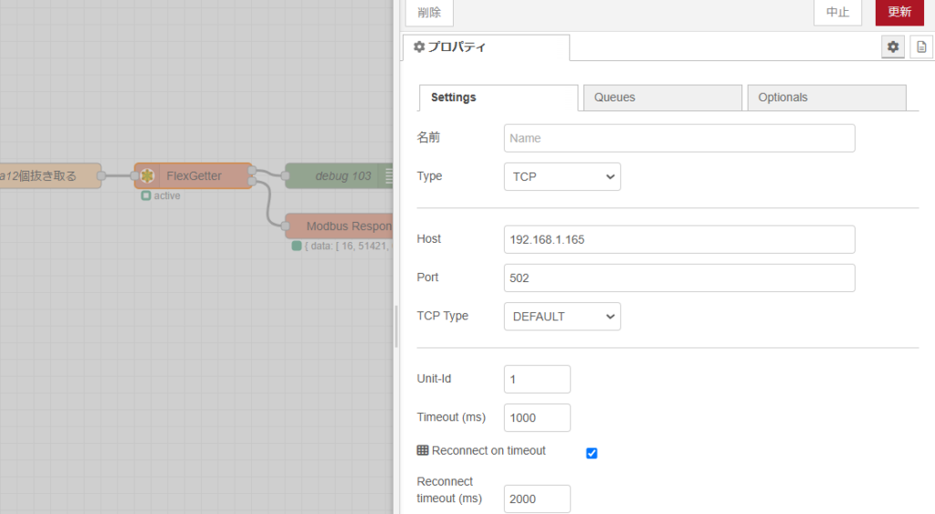
Flex Getter ノードは、TCPモードに設定し、接続先のIPとPortを指定します。

今回、function ノードで12個分のデータを抜き出したため、payloadには画像のようにデータが入っています。
フローはこちら。
[{"id":"d485b5ccb8806da4","type":"function","z":"fbc183746e73c791","name":"data12個抜き取る","func":"msg.payload = { \n 'fc': 3,\n 'unitid': 0,\n 'address': 0 ,\n 'quantity': 12\n };\n\nreturn msg;","outputs":1,"timeout":"","noerr":0,"initialize":"","finalize":"","libs":[],"x":330,"y":220,"wires":[["dcb032a9247b67c0"]]},{"id":"d1ddd819754bbd85","type":"inject","z":"fbc183746e73c791","name":"","props":[],"repeat":"","crontab":"","once":false,"onceDelay":0.1,"topic":"","x":150,"y":220,"wires":[["d485b5ccb8806da4"]]},{"id":"dcb032a9247b67c0","type":"modbus-flex-getter","z":"fbc183746e73c791","name":"FlexGetter","showStatusActivities":false,"showErrors":false,"showWarnings":true,"logIOActivities":false,"server":"b65d0d88ccb88aba","useIOFile":false,"ioFile":"","useIOForPayload":false,"emptyMsgOnFail":false,"keepMsgProperties":false,"delayOnStart":false,"startDelayTime":"","x":530,"y":220,"wires":[["06c5267186c88c32"],["b0a0559c0b495548"]]},{"id":"06c5267186c88c32","type":"debug","z":"fbc183746e73c791","name":"debug 103","active":true,"tosidebar":true,"console":false,"tostatus":false,"complete":"true","targetType":"full","statusVal":"","statusType":"auto","x":710,"y":220,"wires":[]},{"id":"b0a0559c0b495548","type":"modbus-response","z":"fbc183746e73c791","name":"","registerShowMax":20,"x":730,"y":280,"wires":[]},{"id":"b65d0d88ccb88aba","type":"modbus-client","name":"","clienttype":"tcp","bufferCommands":true,"stateLogEnabled":false,"queueLogEnabled":false,"failureLogEnabled":true,"tcpHost":"192.168.1.165","tcpPort":"502","tcpType":"DEFAULT","serialPort":"/dev/ttyUSB","serialType":"RTU-BUFFERD","serialBaudrate":"9600","serialDatabits":"8","serialStopbits":"1","serialParity":"none","serialConnectionDelay":"100","serialAsciiResponseStartDelimiter":"0x3A","unit_id":"1","commandDelay":"1","clientTimeout":"1000","reconnectOnTimeout":true,"reconnectTimeout":"2000","parallelUnitIdsAllowed":true,"showErrors":false,"showWarnings":true,"showLogs":true}]
データの読み方
Modbus Master/Slaveのシュミレーターを試してみた で使用していた、
Modbus Master を使用してデータのシミュレーションを行いました。
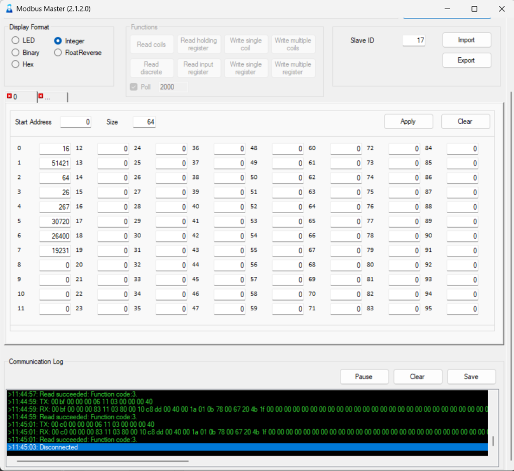
Function として Read holding register を使用してデータを可視化したところ、
RX データのの 10番目から 25番目のデータが読み取られていました。

照らし合わせると上のようになります。

LoRa Button を押してみたところ、ちゃんとデータが変化していることがわかりました。

